

Carbon steel is the most common material to be processed in machining, so most cutting tools are based on optimized carbon steel processing design.The design of such tools must include sufficient chip space without compromising tool rigidity. Cutting edges may be straight or contoured and may be designed for either linear or rotary travel. The most common, among many types of multipoint cutting tools, are the milling, the twist drill, the reamer, the broach, and the gear sharper cutters.
Cutting Tool Design Process
Workpiece shaping occurs as the edges of the cutting tool, driven by the power of the machine tool into the workpiece, force grains of the metal to move away from the advancing cutting edge. This displacement causes the metal to fail. A chip forms along this line of failed metal, which separates from the work material. How such material failure takes place is determined by the following factors :
- Cutting tool design & geometry
- Cutting tool material
- Workpiece material
- Machine forces on the workpiece
- Various process conditions
Cutting Tool Design Process
Workpiece shaping occurs as the edges of the cutting tool, driven by the power of the machine tool into the workpiece, force grains of the metal to move away from the advancing cutting edge. This displacement causes the metal to fail. A chip forms along this line of failed metal, which separates from the work material. How such material failure takes place is determined by the following factors:
- Cutting tool design & geometry
- Cutting tool material
- Workpiece material
- Machine forces on the workpiece
- Various process conditions
Cutting tool design requires an understanding of the application difficulties that can be encountered during the machining process, including:
- Setup rigidity – critical to dimensional accuracy and finish quality of the part.
- Cutting tool strength – must be sufficient to prevent breakage and/or deformation due to anticipated machining forces.
- Weak links – consisting of wear and breakaway members included in the tool design, which limit damage to toolholders and other machine components.
- Machine speed and feed – these parameters along with tool adapter capacity and working clearances all establish restrictions on tool design and production rates. Total cutting force usually resolves into three mutually perpendicular components: feed force, radial force, tangential force, which is the most significant, acts upon the top of the cutting tool, tangent to the rotary direction of the part or tool.
Chip disposal; single-point cutting tools usually have a pressed-in, chip-breaker design to curl and break the material removed into manageable chips. Milling cutters must include ample chip space to hold the chip until it can be thrown or washed out between successive cut passes.
Chatter; results from the momentary separation of the cutting tool and the workpiece. It can cause tool breakage as well as impair surface finish, and can be prevented by eliminating uneven motions and loose fits.
Cutting Tool Raw Material and Grade
The choice of tool material and grade is closely related to the performance of the material being processed, the maximum speed and feed rate of the machine tool. Choose more general tool grades for the material group to be processed, usually coating alloy grades. Refer to the “Grade Application Recommendation Chart” provided by the tool supplier. The cutting tool materials must possess a number of important properties to avoid excessive wear, fracture failure and high temperatures in cutting. The following characteristics are essential for cutting materials to withstand the heavy conditions of the cutting process and to produce high quality and economical parts ;
- Hardness at elevated temperatures
- Toughness: ability of a material to absorb energy without failing
- Wear resistance
- Chemical inertness
- Thermal conductivity
- Surface finish on the tool
Cutting Edge Design of The Tool
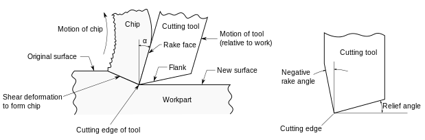
Cutting tool geometries play an important role in tool performance, material flow, cutting force, and cutting temperature distribution.
Cutting edge is the intersection of two tool point surfaces. Cutting Tool is basically a wedge shaped device that actually removes (shears off) excess material from a preformed blank in order to obtain desired shape, size and accuracy. During machining or metal cutting operation, the cutting tool forcefully compresses a thin layer of material of the workpiece and shears it off.
Every cutting tool consists of at least two surfaces, namely, rake surface and flank surface. Rake surface is the chip flowing surface; whereas, flank surface slides over the finished surface of the workpiece. Intersection of these surfaces produces cutting edge.
Single-Point Cutting Tool Design
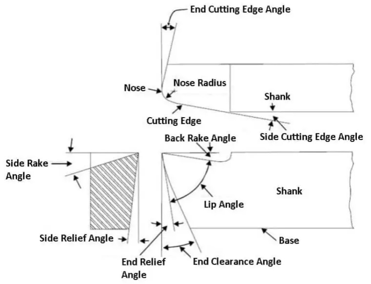
Most turning operations use single-point cutting tools. The nomenclature for a single-point tool is a sequence of alpha and numeric characters, also referred to as the “tool signature”. This signature represents the following tool aspects ;
- Various angles such as the back rake, side rake, end relief, side relief, end cutting and lead angles
- Significant dimensions
- Special features
- Nose radius size
The cutting tool’s nose radius connects the side and end cutting edges. By function, it must be equal to or less than the smallest radius on the finished part. Other factors influencing tool nose radius selection include
- Surface finish requirements
- Tool strength, with the largest tool nose radius permissible giving the highest strength.
While a larger nose radius can absorb more of the generated heat and produce a smoother cut, it can also generate greater radial cutting forces and increase the chance of chatter. In general, the quality of the finished surface results from the proper combination of nose radius and feed per revolution.
Multi-Point Cutting Tool Design
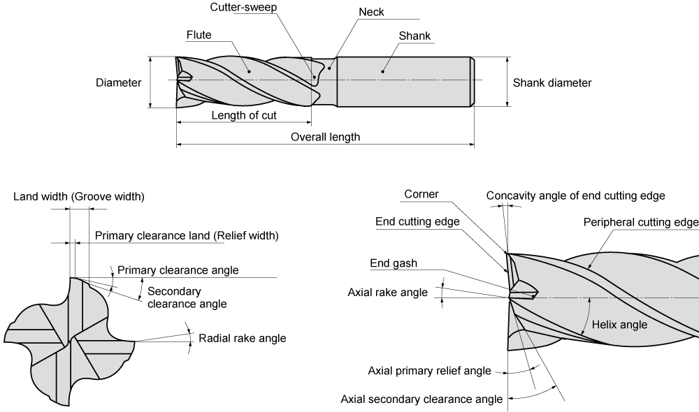
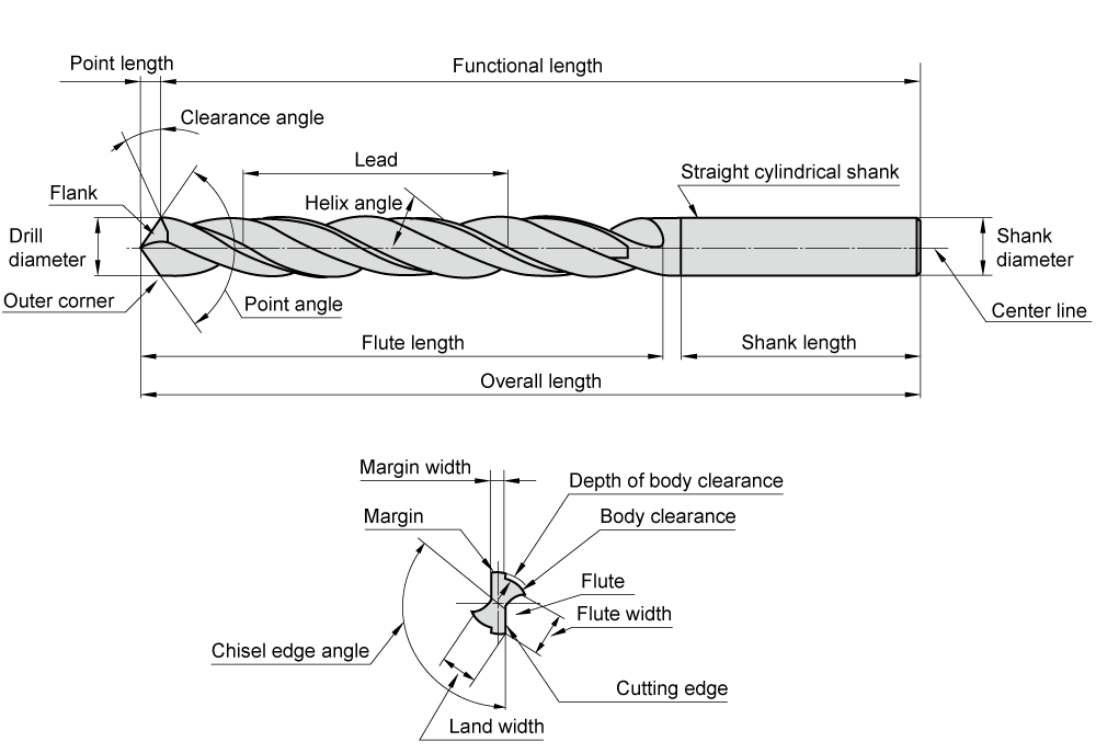
Multipoint cutting tools are comprised of a series of single-point cutting tools mounted in or integral with a holder or body. They are operated in such a manner that all the teeth or cutting edges follow essentially the same path across the workpiece. Most multipoint tools create discontinuous chips that must be carried for some distance over the work before they can be ejected. The design of such tools must include sufficient chip space without compromising tool rigidity.
For more detailed information, please contact with us from the options below.